CAN BUS Project To Interface The MBZ 2007 CLK350.
Or How To Wirelessly Control the Steering Wheel Buttons, Electric Windows,
Door Locks, etc., with a (Windows Mobile) Handheld Computer
I integrated a Windows Mobile handheld computer with a CAN Bus interface and BlueTooth module to control my 2007 Mercedes Benz CLK350 wirelessly. This web page discusses how that was accomplished. Although my car is a CLK, the principles should apply to all late model MBZ and perhaps on most European and Japanese cars since most use the same bus: the CAN bus.
Introduction
When I first bought the CLK350 I was impressed with the technology that went into the car. I normally purchase a service/repair manual with a new car and this car was no exception. After digging into the manual and reading the electrical schematics, I learned that car has no fewer then 4 bus networks and communicates with most of the functions of the auto, such as the a/v system, windows, door locks, etc. Everything including the engine control, brakes, windows, audio system, etc is connected. The networks are 2 CAN busses running at 1 mps and 83kbps, called the CAN-A and CAN-B, respectively, a LIN Bus and a fiber optic network.This got me curious and I had to find out how it all worked. So I bought a book on CAN networks, the Comprehensive Guide To Controller Area Networks , by Wilfred Voss. It is an excellent book and if you want to learn about CAN networks, this is the book to buy and read.
After reading the book, I went through the following steps to approach this project:
- Find a piece of hardware already available to interface the CAN bus
- Find a piece of software that will allow decoding of the bus commands
- Write an application that controls the steering wheel functions
- Modify the hardware to allow wireless connection
- Enhance the bus snooper program to decode the commands for other functions
The details are given below. The result is an application that controls the steering wheel functions totally wirelessly using a bluetooth connection. Although this wasn't accomplished overnight, it has taken about 4 months in my spare time, it was worth the effort as I learned a lot about my car.
Looking for hardware that can interface the CAN bus
This was no minor effort. Ideally, I wanted to buy a low cost kit that contained the hardware and software to snoop the CAN bus in the car. I first searched the web and found a number of kits and modules, all relatively expensive. I finally settled on a reference project kit from Microchip Semiconductor called the CAN-LIN 2 Board. This board consists of two CAN networks, plus a LIN network, and costs about US $100. It also comes with a piece of software called CANKing, which has great potential, but is unfortunately full of bugs. One major bug is it misses frames even at the slow 83kbs. However, it is a great learning tool and found that it came in handy to debug some of my own software. More of that later.
 Missing frames is a major problem and the authors of CANKing flatly refuse to fix it.
I don't know why it misses frames, but I had the same issue with an application I wrote until I figured out the program's methods
(proceedures) being reentrant,
caused arrays to be overwritten before being used and emptied. Thus, the CanKing software wouldn't work and I had to look for
another interface.
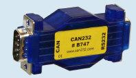
I found the CAN232 built by
Lawicel, AB's CAN232 .
This is a great piece of hardware and at $110 it is well worth the cost.
They have an office in Portland, Oregon but the headquarters is in Sweden.
You can purchase it directly from the office or on the net using a credit card. Unfortunately, it doesn't come with a lot of
usable software.
Missing frames is a major problem and the authors of CANKing flatly refuse to fix it.
I don't know why it misses frames, but I had the same issue with an application I wrote until I figured out the program's methods
(proceedures) being reentrant,
caused arrays to be overwritten before being used and emptied. Thus, the CanKing software wouldn't work and I had to look for
another interface.
I found the CAN232 built by
Lawicel, AB's CAN232 .
This is a great piece of hardware and at $110 it is well worth the cost.
They have an office in Portland, Oregon but the headquarters is in Sweden.
You can purchase it directly from the office or on the net using a credit card. Unfortunately, it doesn't come with a lot of
usable software.
Lawicel's hardware comes in two flavors, the CAN232 and the CANUSB. I bought the CAN232 ($110 + s&h) instead of the CANUSB (about $154 + s&h), because it is cheaper and I already have a USB to serial adapter. It turned out that was a good choice as it became handy to have the serial port to interface it with the bluetooth module. More on this later.
Find a piece of software that will allow decoding of the bus commands
The CAN232 website has some downloadable projects. Since I was interfacing with a Windows XP, the number of projects are limited. I tried the existing CAN232 Visual Basic program, but it has a multiple of limitations. One of these is the only serial ports it connects to is COM1 or COM2. The other major one is it doesn't allow bus connections at 83kps, the speed of the CANB on the CLK350. Bummer.
CAN232 VB program had to be modified. I'm an Electrical Engineer by trade, but most of my career has been in writing software so I undertook this task. The modification took a little time but was very successful. CAN232HSW is now available to anyone who wants to use it through the creative commons license (see below).
You can get it here along with all the Visual Basic source code ... CAN232HSW.
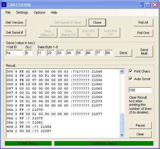
The CAN232HSW Visual Basic Program
Creative Commons License.
This means you may use it at will, modify the code or whatever you would like to do with it. However, if you use any of the code for commercial use, you must give me and Lawicel credit.
Perhaps, an explanation of what the PID's are is in order here. Trying not to insult your intelligence, the PID is the address of a given module. A module could be, for example, the window buttons on the drivers side. When you push the window button the PID is sent on the buss along with data indicating which button you pushed. For the CAN bus, there can be one to eight bytes of data.
CAN232HSW is used to spy on the bus and read all the frames that was applied by the different car systems. The amount of data was enormous. The PID's (ID's) have to be decoded since manufactures of autos usually won't publish the ID or the meaning of the values sent out by them. Something about liability. Different techniques have to employed to figure out the ID's. For example, by continuing to push the one or many of the steering wheel buttons, I looked for any changes on the data bits within a given PID. For example, I finally stumbled on the correct PID for the steering wheel, 1A8 (hex). Then a filter was added to list only PID 1A8. The bit value of each of the buttons was determined by pushing each of the buttons and recording it.
Another technique which I strongly recommend is to use the pids that other people have decoded. One was done by Attila Vass as his "Toyota Prius Project". Read more about the Prius project Toyota Prius project . He has some great linux programs written mostly in C that you may be able to use. He has also decoded many of the Toyota pids which will come in handy. I followed a lot of the techniques Attila used and have to give him credit for the methodology.
Write an application that controls the steering wheel functions
I wanted some flexibility to decode the PID's and data, so an application to give that to me need to be written. It is written in Visual C++, since that is the language I know best and it allows many more coding tricks. I had a feeling that I would need to grab some of the Windows messages and do some pre-filtering of the system messages. I was correct. Since I needed to replicate the steering wheel button functionality exactly some programming tricks need to be added. For example, I wanted the program to recognize that I was continually pressing the button for the steering wheel function "+", which raises the sound volume, so the PreTranslate method was overridden. This would be difficult in Visual Basic.
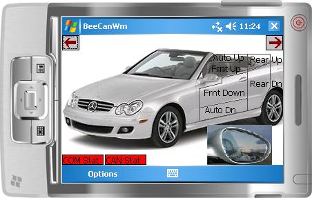
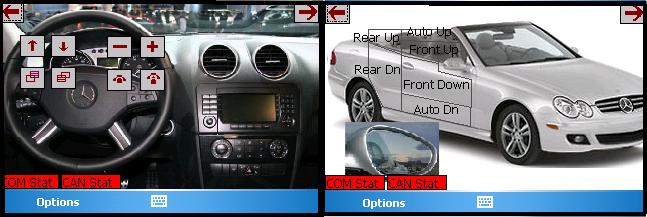
The program interface looks a little primitive, but here is another one of several different views:
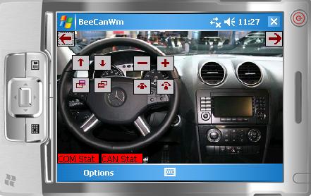
All the car's steering wheel buttons are replicated using a standard window's control and a little image of each is placed on top... nothing fancy. By clicking on one of the buttons, the corresponding steering wheel function of the car operates. For example, clicking and holding the "+" will increase the radio's audio volume and the program the button being depressed. The program works great.
Even though the application interface is overly simplistic, it can be used to build on and add more functionality at a later date. I plan to modify it add more functionality the more I learn about other PID's.
Modify the hardware to allow wireless connection
After playing around with the car functions and getting it to work, I had to show this to my wife. Basically, all she said was "why are there so many wires". She's right. The unit requires a serial cable to the laptap, a power source to the CAN232, and the two CAN bus signals. Too many wires. I had to address this.I own a BlueTooth FireFly module. This is a basic BlueTooth interface that converts BlueTooth to RS232 serial. Quite a nice device, so I thought it might work on my CAN232. At first attempt it didn't work. It took a about 6 hours to discover why, which is my fault because I should have realized it at once. The CAN232 is configured for 3 wire connection, but the FireFox was connected originally for hardware handshaking, i.e. it used DTR, CTS. After d/l the FireFly instruction manual, the device was configured for no hardware handshaking. A couple of dip switch changes later, the device was working with my favorite Windows terminal emulator program: remember ProComm? However, the CAN232HSW program didn't work. Back to debugging.
Turns out the CAN232HSW used a library called MSCOMM. The library is incredibly convenient to implement, and whoever wrote it deserves a lot of credit, but it didn't work. Why? I still don't exactly know why, however I think the IVT Bluetooth driver in the handheld computer uses overlapped serial transmission and doesn't set up the call buffer quite right. MSCOMM program didn't handle the serial Overlap interface and relied on the standard call, soooo the data wasn't read properly.
To solve this, I ended up changing the "SerialPort" library supported in Visual Basic. It took about 3 hours to do the code modifications. It could have taken less time but I'm not familiar with this library. Now it's working again. The version of CAN232HSW you can d/l includes the change in the library.
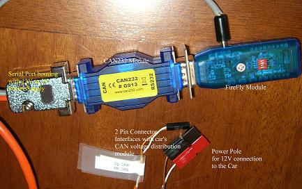
I also had to build a power supply for the FireFly. The CAN232 uses a 12V supply powered which is supplied by the car, and the FireFly needs between 5V and 9V. I took a 7805 voltage regulator, available from Radio Shack, and wired into the RS232 connector . The result is shown in the picture above. The module hides just under the dash below the drivers seat. Power is switched and taken from the cigarette lighter. Power wires have Power Pole connectors, only because I really like to use these babies since it is quick to connect and the module can be taken out of the car whenever needed.
You can use whatever bluetooth adapter you can find for the laptop or handheld computer. I found the IVT BlueSoleil host software very convenient and it works well. The FireFly's serial port is established as soon as the application opens the serial port. When the application terminates, or the serial port is closed, the bluetooth connection stops. Really nice.
I discovered only a few of the PID's for the CLK350 Mercedes so far. You can download the ones I know in this spreadsheet known pids for the Mercedes Benz CLK350 (updated 10/30/2008). It will get you started.
BeeCanNav Program
Attila wrote a program to plot the number of times a PID was used and to graphically display the data. I took a slightly different approach and wrote an application that sorted the PIDs and displayed the data as it was changing in character form in real time. I was able to tell when the data changed just by looking at when the display line flashed. Here is an example of the interface of that program: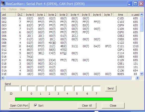
BeeCanNav Program. PID's are sorted by ascending value with data displayed in real time. "Time" column gives a relative indicator when the data last changed, and "x used" column gives a count of the number of times the PID frame was sent.
The program helped enormously by concentrating on a single PID at a time, moving a car control and watching for data movement. BeeCanNav is available for download under the creative commons license (see above for what that means). Feel free to use it for personal use.
The download is the executable only. If for any reason you want to see the source write and ask. The source is written in VC++ and MFC using Visual Studio 2008. You will need a copy of VS2008 to modify and read it so if you don't have VS please don't ask.
Future Work
So much to do and so little time. So why am I wasting my time writing up this page. We'll, I'll answer that. Hopefully if you are reading this, you find it useful. Hopefully, I can be of some service and you can leverage some of the work I've done. If you find this exercise interesting and you learn something, then this effort has been worthwhile. Good luck in your hacking of the car and hope you have as much fun as I did. I learned a lot about my automobile as complicated as it is. I feel I have a better appreciation of what the automobile engineers went through designing it and what the auto mechanics will go through trying to identify and fix a problem. It also gives me an appreciation of why there are so few aftermarket add-ons for this and all other newer cars that are on the market. You almost have to be an electrical engineer to understand the system, let alone design something for it. Good luck in your endeavors. Hope they turn out well.
System Requirements
The system requirement for all this is minimal. Windows XP or Vista, if you can run XP you have enough memory and CPU speed. Oh, and a car with a CAN bus.