Just say "Alexa - Open Shades"
|
Open or close your shades using Alexa:
This project uses parts that you can buy from the internet or from your local electronic parts store. |
Web interface | ||
|---|---|---|
| There is also a web interface in case Alexa is down or your away from home. The web interface is a simple html page and is generated inside the code. If there is no POST request the code writes the page. It also displays the state of the motor control and the value of the current of the motor as measured across the 1ohm resistor (see Schematic below). lines at the time the page is generated. Just point your browser to the home IP address of the shadecontroller. |

|
|
The Complete Description
Electronics: Inside the Control Box |
|
|---|---|
|
To begin with here is the orange box that contains all the electronics mounted on the casing of the window with a single screw.
The box contains a Wifi chip and the microcontroller. The microcontroller is a ESP32 development board. The schematic is simple and easy to wire with just moderate skill of the developer. It uses only two wires from the ESP32 plus power. One controls the the directiof the motor, either clockwise or counter clockwise, another uses the AD converter on the chip. All html for the web pages are placed in the microcontroller. There is a handshake method between the Wifi chip and the microcontroller. When the Wifi chip requires an html page the appropriate page is transmitted by Wifi onto the web. The IC below the ESP32 is a motor controller as shown in the schematic below. This IC controls the direction and the voltage to the motor. |

click for a larger view |
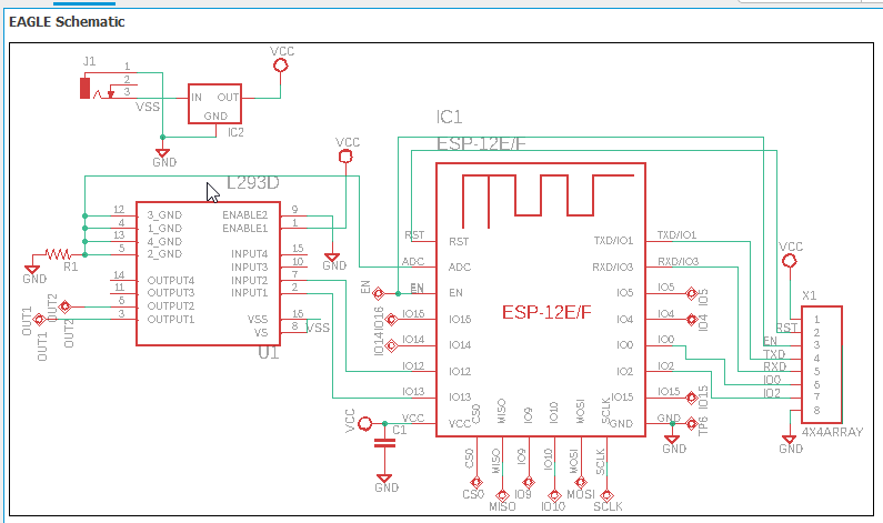
The Schematic |
|
|
For those who want to copy or understand the schematic here it is. It's pretty simple
and a lot of explanation is not needed. The ESP8266 and the microcontroller are both
3V so the power has to be reduced from the 5V input to 3V which is done by the regulator.
The sensor is 5V, however. The 5V output of the sensor feeds into a 5V tolerant input
of the processor which is, by the way, another good reason for using the microcontroller.
Other than that the schematic is pretty straight forward.
The Out1 and Out2 are the pins for the motor. Doesn't matter which goes to what motor lead since the firmware will reverse direction once the motor "bottoms out". Don't think I need to say more because the schematic says volumes. Except the schematic shows a ESP12. I actually used a ESP32 Development, or you can build a PC board with a slightly less expensive ESP8266 as shown in the schematic. The code is the same with the exception of the pins. |
click for a larger view |
Parts List
If using the the ESP12
|
|
CodeThe code is pretty straight forward. It is basically just server code written in an ESP32. The one tricky part is determining when the shade is open or closed. When the shade is closed, open is determined by a timer. After initiation a timer is set and the motors are shut off after a certain amount of time. To determine if the shades are closed is a little more complicated. Look at the schematic. R1 resistor senses the current the motor is drawing during operation. The current is relatively low when the shades are moving. If the shades reach full open or closed position the current will increase due to the load of the motor. The code then knows to turn off the motor. If you desire to see the code, write for it. I'll freely send you a copy but is seems totally unnecessary to post it here. |
|
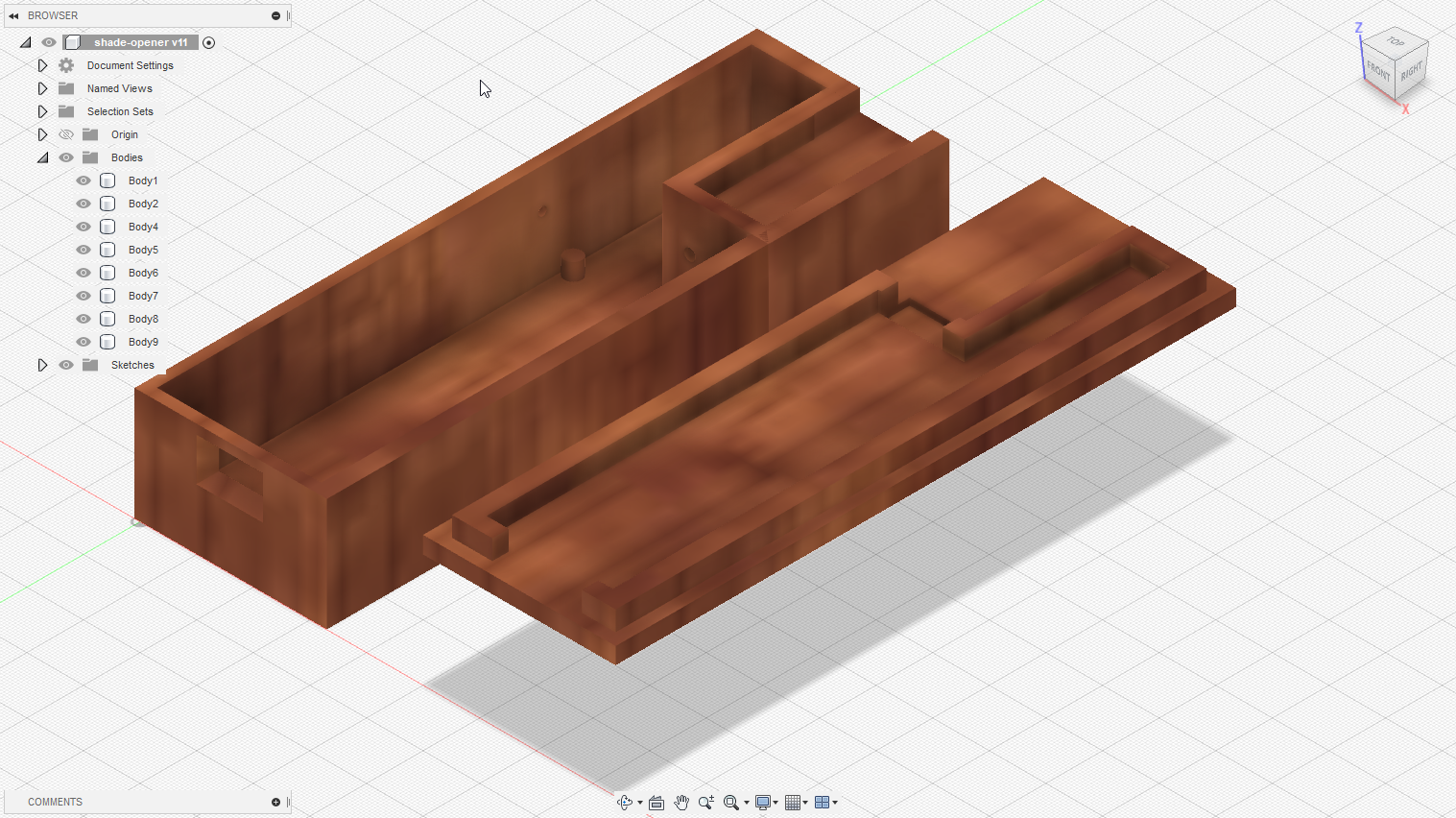
CaseThe case was done in Autocad's Fusion 360 and printed on a 3D printer. The case has a cavity that holds the motor tightly, shown in the upper right. The cavity was originally designed to hold the motor from turning but the fit is tight enough to allow the motor to sit inside without external mounting screws.There is a hole on the left side for a screw that attaches the case to the window casing. The lid is also shown. It has ribs that fit inside the walls of the bottom case. There currently isn't anything that fastens the top to the bottom case, although the ribs are long enough for a screw. Since there is little vibration when opening or closing, the lid doesn't work itself off. |
click for a larger view |