Yet Another CNC Home Built Router
A YouTube video that further shows the current status.
Or how to build a CNC router in your tool room using some
tools you have around, like a welder, power metal saw, soldering iron,
etc.
by Howard Honig,
Honey Software LLC
Introduction
November 22, 2012Warning: Much of this is just outline. Only a small fraction has been written. If you find this sight before it is finished, and you have an interest in this project, come back often as it will be updated on a regular basis.
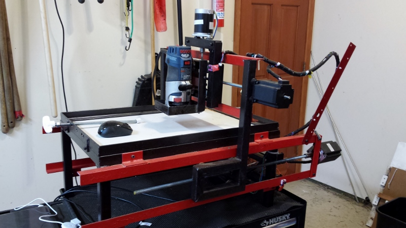
I am currently working on a home built CNC router. Somehow, I got the idea that a cnc router would be nice to have and I didn't want to pay the $3k minimum a purchased one would cost. So I'm using the poor metal working skills I have building it in angle iron and square steel stock. The router itself is a purchased DeWalt router hand router that has been adapted. The design is my own.
The above picture was taken before painting and before the motors have been attached. I'm currently painting it and waiting on the stepper motors. There still is a lot more work to do, as you can see.
The Hardware Design
This was no minor effort and the design is in the early stages but I wanted to get something written while I had some spare time.To do the design I checked a number of home build routers by some very talented people who published something on the web and who took the time to do videos and publish them on YouTube. They were all good ideas, but I wanted to do something a little differently and with hardware that I am familiar with.
I drew up dozens of different plans before starting. None seem realistic until I can up with this one. It is too early to tell whether this one will work or not, but it seemed worth trying. It is made up of 1" angle iron steel and square stock steel all purchased from a local supplier in Albany, Oregon.
The dimensions are pretty arbitrary but the width of the Melimine insert board defined the width of the table. The length was determined by looking at the aspect ratio and what looked ok. Pretty inelegant, isn't it? So far though, it is looking pretty good.
Some of the parts are welded and others are drilled, tapped and screwed. If I think there will need to be an adjustment, as in the rails, the pieces are drilled. The basic platform is all welded, however, to give it strength.
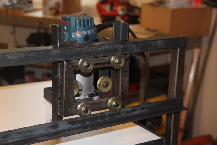
The rollers you see in the picture are rollers used for sliding glass doors. I got these at Home Depot for about $7.00 for two. Compare this with the $13 or so you would pay for a roller bearing wheel at some of the websites. There is a downside in that there is more play in the bearings then I would like to see, plus the channel is wider then it should be, but the channel is deep enough, so that may be ok. I'll see once the motors are on and working.
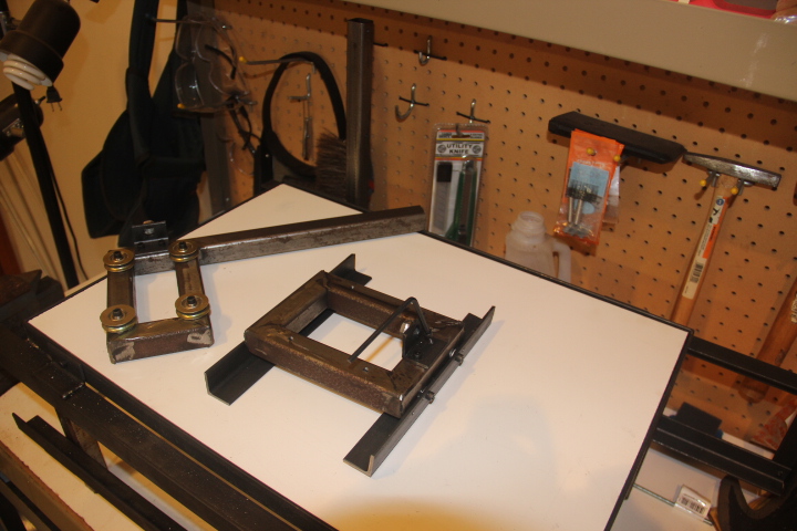
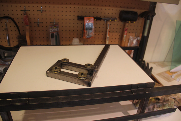
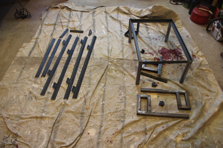
Here are a few pictures of the pieces when the unit was taken apart to paint.
|
|

|
|
|
|

Parts layed out for painting |
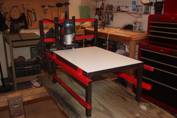
After painting |
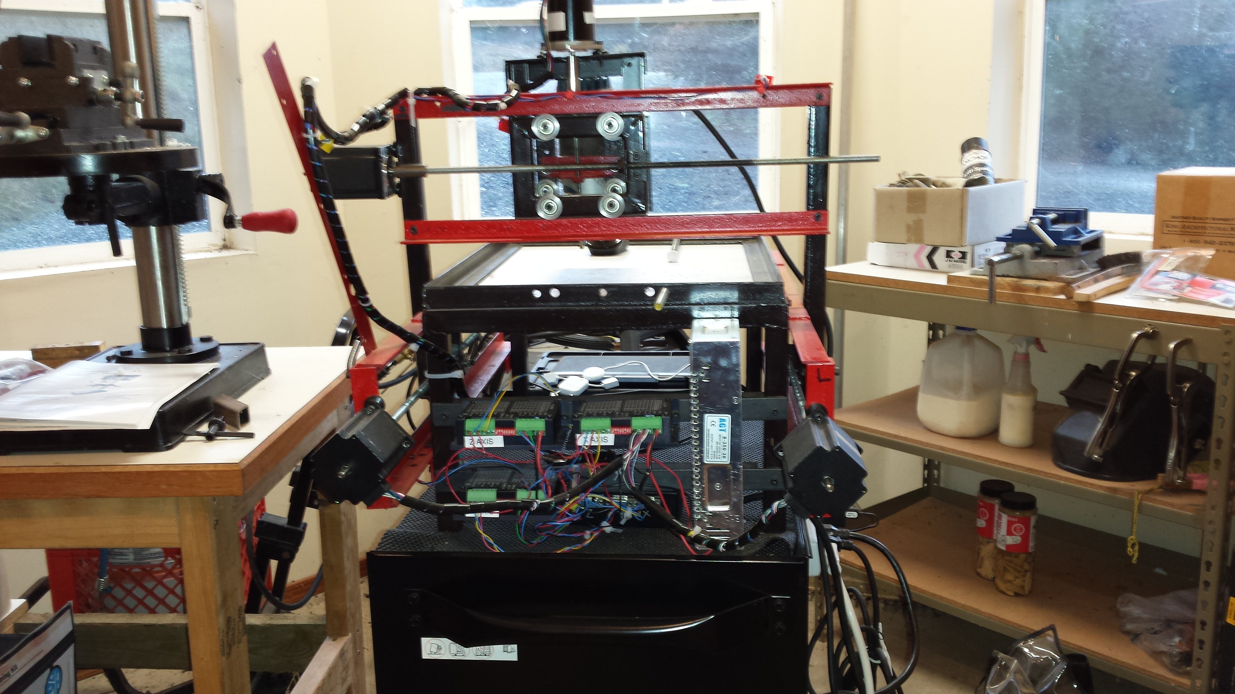
Rear View |
The Motor Control Circuit
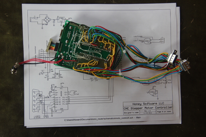
The stepper motors have to be driven. To do so there will be a circuit controlled by a Microchip PIC18 with the circuit similar to the satellite antenna. It hasn't been designed and built yet, so stand by. Here is the board sitting on the schematic. The full schematic will be shown in a couple of days.In case you are wondering, the board is a Olimex Pic development board. It comes with a Pic socket, a Max232 for serial RS232 to the Pic and a prototyping area. The portotyping area is what I used to build up the circuit.

|
|
The Motor Control Circuit
The stepper motors have to be driven. To do so there will be a circuit controlled by a Microchip PIC18 with the circuit similar to the satellite antenna. It hasn't been designed and built yet, so stand by.The CNC Controller
What I really need now, to test it out with a CNC Controller program. There are a couple for about $100-$200, but they are for interfaces that are different then what I want to build. KCAM and MACH3 are two, but I'm not sure I can adapt what the output it supports. It interfaces with a couple of CNC controllers, but the controllers are expensive. Plus it requires a Parallel port and that is impossible to find on all the new computers. That is why I need to build my own.I'll be writing this in Visual C++ using Microsoft Visual Studio. It won't be easy but should be worth the effort.
The CAD Software
Visual CAMM would be perfect for this project, I would suspect. As you probably are aware there are a lot of CAD programs available. I check out Turbo CAD from Imsai, and there are cheaper ones available. I was thinking of using CADStd since it is free, but there is no control of Z axis and there is no tool files. This means I would have to add Z to the G-Code that is generated from the free program DXF2Gcode available from Google code. CADStd does export a DXF file however. Another option is the 3D FreeCad which is available from sourceforge. Unfortunately, FreeCad also lacks tool controls so offset has to be added in the GCode. In addition even though FreeCad is very elegant its interface is hard to learn and it crashes a awful lot. All a bummer. I wouldn't mind purchasing Turbo Cad but the tool file is an ad-on and $$$.I don't mind spending money on all these better tools but I don't even know if my router will work well, yet. This may be a chicken-and-egg problem.